Hardware Hacking
Tools
- USB-TTL UART converter: This can be used to debug and test various systems. It can be wired up and configured for different logic voltage levels.
- CH431A USB programmer: This can be used to flash firmware on devices such as BIOS, routers, etc.
- Jtagulator is an open source hardware tool that assists in identifying OCD interfaces from test points, vias, component pads, or connectors on a target device.
- Spudgers - Plastic tools for prying apart plastic components without damaging them (hopefully). These are engineered to break before your device does.
Tutorials
- Using UART pins to get a root shell (YouTube)
- Finding UART interface (YouTube)
- Getting a root shell via UART (River Loop Security)
- Hackers Guide to UART and Root Shells (YouTube)
- Using the CH431A programmer to copy the firmware from a device (YouTube)
UART
A UART is a chip or sub-component of a microcontroller which provides the hardware to generate an asynchronous serial stream such as RS-232 or RS-485.
Common Use:
UART is widely used for serial communication between devices, such as between a microcontroller and a PC or between two embedded systems. It's frequently employed during development for debugging, allowing developers to monitor program execution through a serial console or send commands to the system in real time.
Why it's Found in Devices:
- Logging and Debugging: UART is often used for outputting debug information, known as a "serial console," which provides valuable insights into system behavior during development or runtime.
- Device Communication: It can serve as a communication link between the microcontroller and peripherals like sensors, modems, or other embedded devices.
- Runtime Interaction: UART allows developers to send and receive data while the device is running, making it useful for issuing commands or monitoring status without needing to pause or stop execution.
Frequency:
- Extremely Common: UART is commonly found in microcontroller-based systems, such as Arduino or STM32 boards, because it offers a simple, low-overhead way to communicate with external systems.
- Serial Monitoring: During both development and post-deployment, many systems provide UART interfaces to monitor device activity and for debugging via a serial terminal.
Typical Applications:
- Embedded System Debugging: Developers often use UART to read log messages or system status while the device is running.
- Peripheral Communication: UART is used to link embedded devices with peripheral modules (e.g., GPS, modems).
JTAG
JTAG: Joint Test Action Group, is an industry standard for testing and debugging electronic systems.
Common Use:
JTAG is primarily used for hardware debugging, programming, and boundary-scan testing of integrated circuits (ICs), microcontrollers, and FPGAs. It gives developers low-level access to the internals of a chip, allowing them to directly manipulate registers, step through code, and flash firmware. JTAG is a key tool during the development of complex systems and is heavily used in manufacturing for testing PCBs and chips.
Why it's Found in Devices:
- Programming and Debugging: JTAG is crucial for flashing firmware onto devices, especially during initial development. It's used to deeply inspect the inner workings of the system, such as registers and memory, during debugging.
- Boundary Scan: JTAG is used in manufacturing to test and verify that the circuitry on PCBs is functioning correctly by probing the state of individual pins on the chip.
- Firmware Updates: It can also be used for updating the firmware in systems that require low-level access to flash memory.
Frequency:
- Common in Complex Devices: JTAG is typically found in more sophisticated embedded systems, such as those using FPGAs, microcontrollers, or SOCs, especially when development requires low-level access to the chip.
- Development Boards: Many development boards for microcontrollers and FPGAs have JTAG interfaces exposed for easy debugging and programming.
- Post-Manufacturing: While JTAG is often not accessible to end-users in consumer products, it's used heavily during manufacturing and testing.
Typical Applications:
- Embedded System Development: Developers use JTAG to step through code execution, set breakpoints, and inspect registers at a low level during debugging.
- Manufacturing: JTAG is used for boundary-scan testing of PCBs and integrated circuits to ensure that all connections and components function correctly.
- Firmware Flashing: JTAG is also used for programming firmware onto devices, especially in early development or when a system needs recovery or reprogramming after an issue.
JTAG pins
Here is an example of a router's PCB:
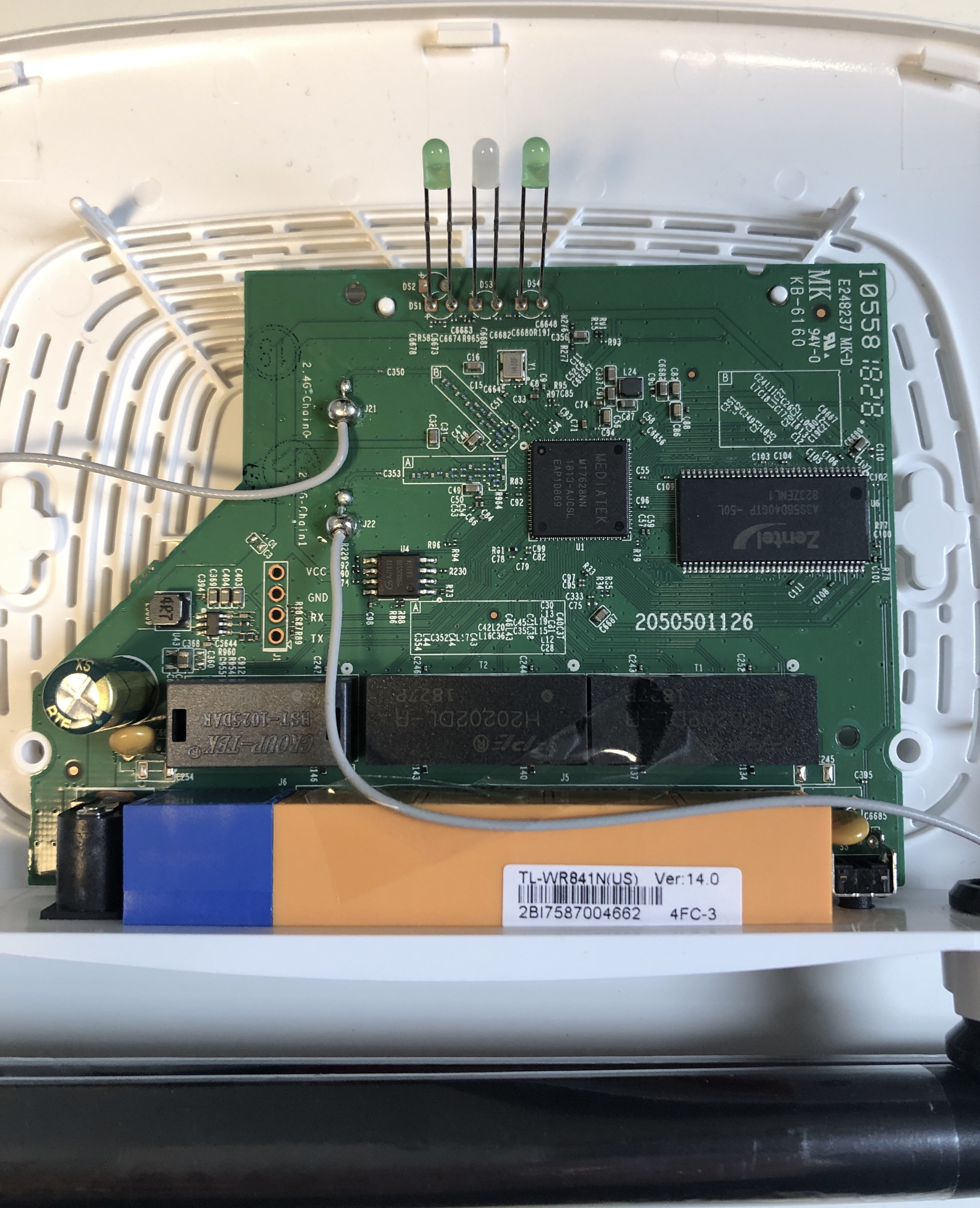
On this router's circuit board, the debug header is labeled (VCC, GND, RX, TX). They are often not labeled and are sometimes hidden amongst other headers. Identifying them can be done with a logic analyzer.
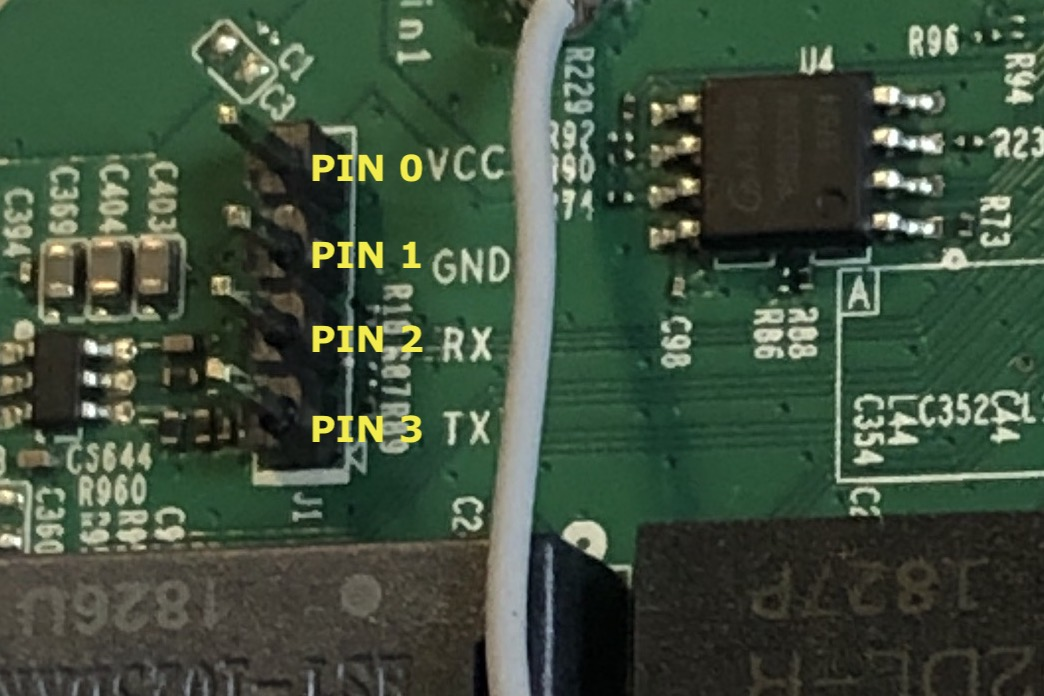
In this case, some header pins were soldered onto the board to make it more accessible.