Arduino
These are the materials for my Arduino for Beginners workshop. There is more here than will be covered in the workshop so explore and enjoy.
Workshop Needs
- Laptop (your own)
- Arduino
- USB A to B cable
- Breadboard
- Jumper wires
- 220 Ω resistors
- 10K Ω resistors
- 1 x LED
- 1 x Potentiometer (knob)
- 1 x hobby servo
Internal Resources
- Arduino Workshop Outline - Arduino for Beginners workshop at Jacobs Institute
- Arduino Presentation - presentation slides for the workshop
- MaxMSP and Arduino if you're interested in using Arduino with MaxMSP, an electronic music programming suite
External Resources
Parts
- Sparkfun lots of parts that work well with Arduino and other microcontrollers
- Adafruit another source of components that work well with Arduino and similar microcontrollers
Basics
- Arduino.cc the organization's website.
- Arduino.cc Language Reference to look up functions and how they should be used
- learn.Adafruit.com - Adafruit's educational resources
- Arduino Get Started
- How to use an Arduino (ScienceBuddies.org)
- The Basics of C++ on an Arduino (DigiKey)
Videos
- Arduino Quick Intro (Robonyx, 9 min)
Projects
- Hackaday.io for various projects
- The Robotics Back-End (various projects)
- Automated Window Curtain
- LED Mood Lighting controlled via an app or motion sensor
What is an Arduino?
First, what is a microcontroller? Originally, microcontrollers were one-time-programmable logic controllers. Some code is compiled and loaded into the device and that code is the logic of how input and output signals are handled. Some version of a microcontroller is at the heart of any embedded system - e.g. home appliances, cars, gaming devices, etc.
The first reprogrammable microcontroller was the Parallax Board of EducationSparkfun. 15 Years of SparkFun: The Origin Story.
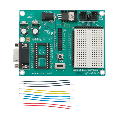
The re-programmable Parallax Board of Education and jumper wires
Arduino is an open-source electronics platform based on easy-to-use hardware and software. Arduino boards are able to read inputs - light on a sensor, a finger on a button, or a Twitter message - and turn it into an output - activating a motor, turning on an LED, publishing something online. You can tell your board what to do by sending a set of instructions to the microcontroller on the board. To do so you use the Arduino programming language (based on Wiring), and the Arduino Software (IDE), based on Processing. Once finished with a prototype, the board can be reused in the next project and new code sent to the microcontroller.

An early Arduino board
Arduino was born at the Ivrea Interaction Design Institute in Italy as an easy tool for fast prototyping, aimed at students without a background in electronics and programming. As soon as it reached a wider community, the Arduino board started changing to adapt to new needs and challenges, differentiating its offer from simple 8-bit boards to products for IoT applications, wearable, 3D printing, and embedded environmentsArduino. What is an Arduino.
Modularity is the main reason why Arduino and the vocabulary of components that interface with it have become well known as tools for prototyping. It is an easy way to test an idea, create a working concept design.
Examples of embedded systems
- mp3 players
- digital cameras
- washing machines
- voting machines
- video game consoles
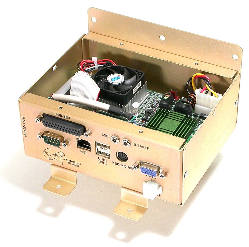
Embedded computer subassembly for Accupoll Electronic Voting Machine
Types of Arduino boards
The Arduino organization manufactures multiple variations, such as the Arduino Nano's smaller form factor. The There are lots of clones of Arduino and they should all work with the Arduino IDE. If they say "Arduino compatible" it should work with the Arduino IDE.
What do you need?
- One Arduino Uno (provided in workshop)
- One USB-A to USB-B cable (connected to the Arduino)
- One breadboard, some jumper cables, electronic components (provided in workshop)
- One computer with a USB-A port
- Arduino IDE
Breadboard
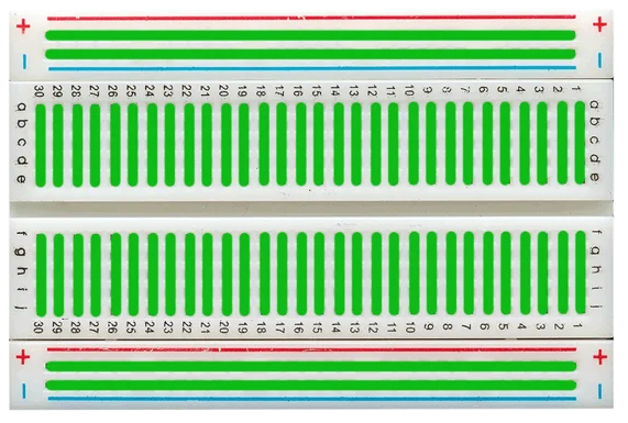
Breadboards are for ideation and proof of concept. Once you have your design you can fabricate it with more permanent connections.
Basic Safety Recommendations When Using an Arduino
-
⚠️ Avoid short circuits: Do not let the 5V or 3V wires (usually red) and ground wires (usually black) touch. This will cause a short circuit and can damage your Arduino.
-
⚠️ Your Work Surface Matters: Make sure that the surface you are working on is not conductive as this can also cause short circuits. The best materials for work surfaces are wood or laminate. One can add an anti-static mat (ESD mat) to prevent the buildup of static electricity that could damage sensitive components.
-
⚠️ Disconnect Power During Assembly: Always disconnect the Arduino from its power source (USB or external) when making or modifying circuit connections.
-
⚠️ Use Proper Resistors: Always include resistors when using LEDs or other components to limit current and prevent damage.
-
⚠️ Avoid High Voltages: Do not expose the Arduino to voltages higher than 5V (or 3.3V for some boards) on its digital pins.
-
⚠️ Prevent Overloading Pins: Arduino pins can typically handle a maximum of 40mA, but it's safer to keep the current below 20mA per pin. Use transistors, relays, or MOSFETs to control higher loads.
-
⚠️ Handling malfunctions and errors: In case of a malfunction or unexpected behavior, disconnect power immediately and check connections.
-
⚠️ Component Datasheets: Manufacturer's datasheets are very helpful when you need to understand a component's specifications and limitations of the components you’re using (e.g. power requirements, what each pins are for).
Sensors (Inputs)
- potentiometer
- photo-resistor (light sensor)
- photodiodes
- force-sensitive resistors
- switches
- buttons
- keypads
- joystick
- temp/humidity sensors (DHTxx)
- radio receivers
Actuators (Outputs)
- Stepper motors
- Solenoid
- DC motor
- Positional servo
- Continuous servo
- Linear Actuators (another)
- Radio transceivers like nRF24L01 - a popular, low-cost RF module that sends and receives in 2.4 GHz, can work across several kilometers
- SparkFun soil moisture sensor
- SparkFun Sound detector (available on Amazon cheaper)
- Controllable Outlet Relays the safe way to control devices that require wall power
- Air quality sensors at SparkFun
Arduino Diagram

Digital I/O pins
Each digital pin can be programmed to act as inputs or outputs.
Analog Pins
These
Resistor Values
Resistors are labeled with colored bands representing their resistance value. Resistance is measured in ohms (Ω).
For a 4-band resistor:
- Band 1 & 2: Significant digits
- Band 3: Multiplier (e.g., ×10, ×100, etc.)
- Band 4: Tolerance (e.g., ±5%)
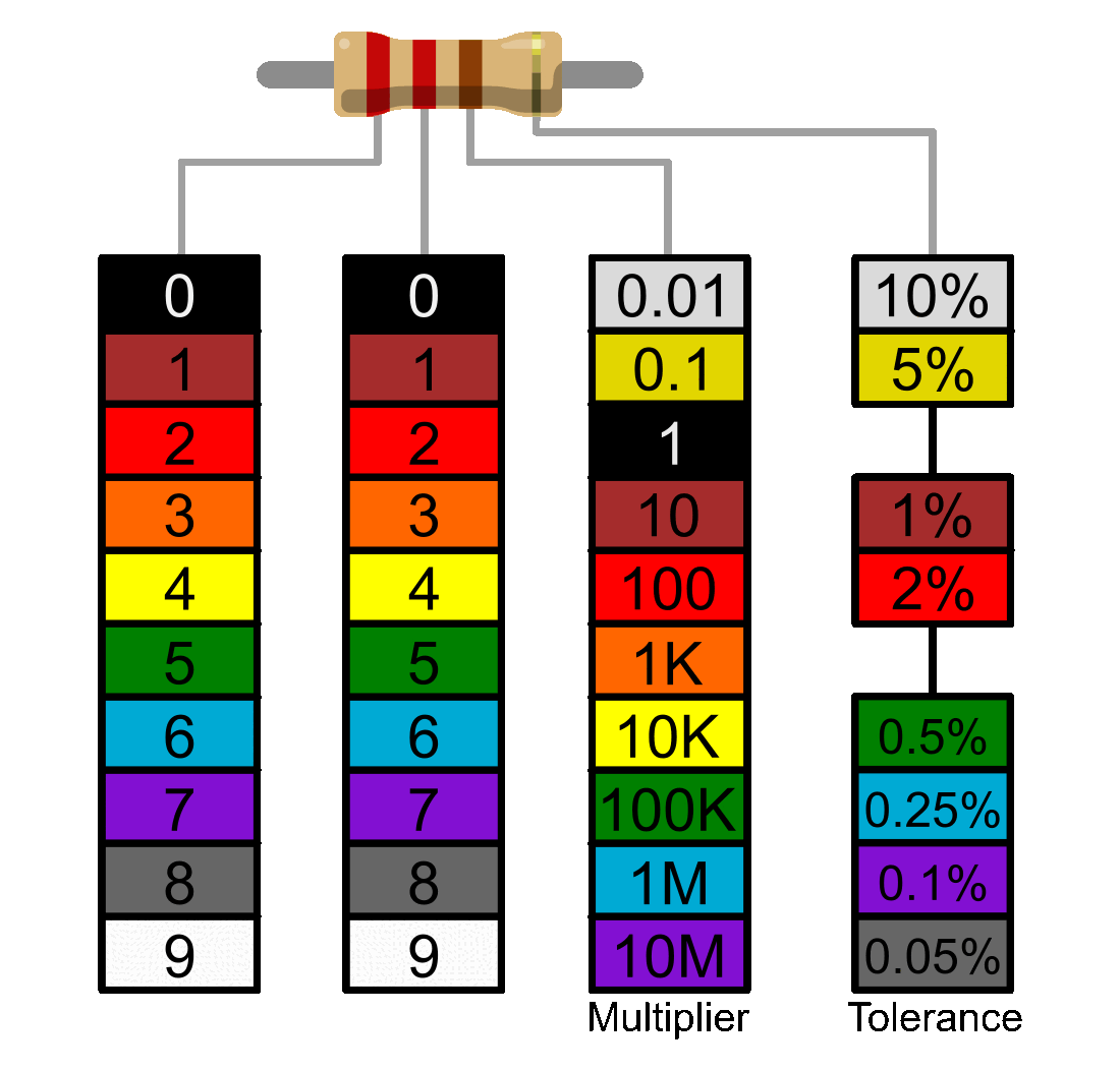
A four-band color code - this is a 200 Ω resistor
5 bands on the resistor:
If there are 5 bands, then the third band signifies a third digit.
- Band 1, 2, and 3: Significant digits
- Band 3: Multiplier (e.g., ×10, ×100, etc.)
- Band 4: Tolerance (e.g., ±5%)
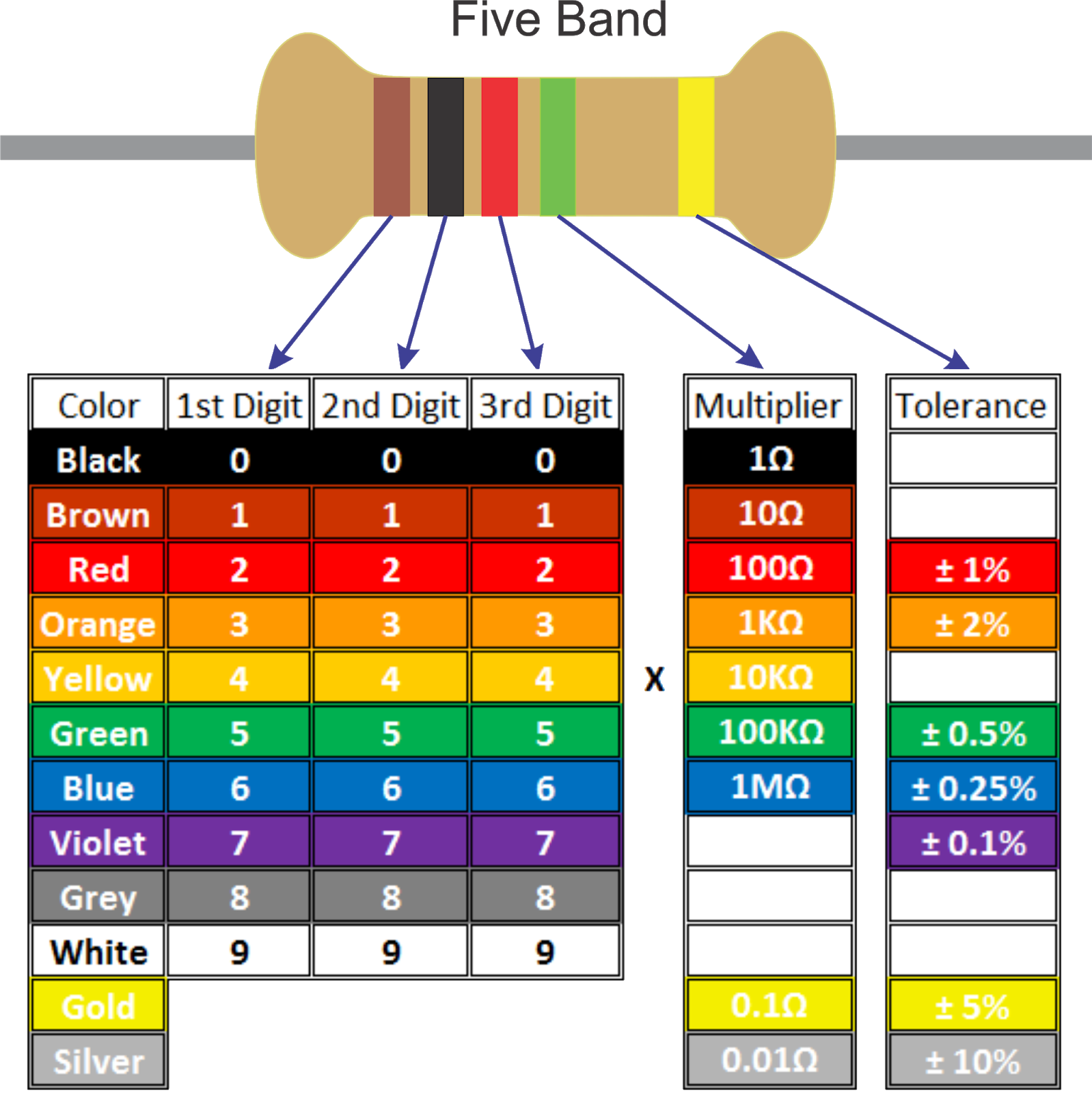
This is a 10.2M Ω resistor
How this process works
- Create the circuit on your breadboard using jumper wires and other necessary parts (resistors, sensors, etc.)
- Open the code (*.INO file) you intend to write onto the Arduino.
- Make any changes to the code that are necessary to match your circuit
- Before uploading the code, disconnect the jumper wires that are directly connected to the Arduino (5V, GND, and any analog/digital pin wires). This can avoid errors during the upload process.
- Verify the code. If any warnings/errors come up, fix those.
- Upload the code.
- Reconnect the jumper wires from the Arduino to your breadboard (5V, GND, and pin cables)
Writing to Digital Pins
Digital pins on an Arduino can be used to control components like LEDs, relays, or motors by sending either a HIGH or LOW signal. More (Arduino.cc)
Step 1: Identify the digital pin you will use
Step 2: Connect the component (e.g., an LED) to the pin
There are three modes digital pins can be set in:
- OUTPUT
- INPUT
- INPUT_PULLUP - This option is the same as
INPUT(you read data from the sensor), but in addition to that, an internal Pull-Up Resistors – between 20k and 50k Ohm – is enabled, to keep the signal HIGH by default. This helps with signals which can be a bit random like pushbuttons. More info
The pins on the Arduino can be configured as either inputs or outputs. It is important to note that vast majority of Arduino (Atmega) analog pins, may be configured, and used, in exactly the same manner as digital pins.
One can send "on" or "off" signals as HIGH or LOW values to a digital pin that is configured as an OUTPUT. its voltage will be set to the corresponding value: 5V (or 3.3V on 3.3V boards) for HIGH, 0V (ground) for LOW.
pinMode(pin, OUTPUT);      // set pin to output
digitalWrite(pin, HIGH);
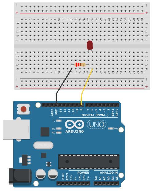
Example 1: LED blinking
Objective: Learn how to control an LED using digital pins by writing HIGH and LOW signals.
There is a simpler example in File > Examples > 01. Basics > Blink which uses an LED that is already built into the Arduino board. This requires no parts beyond the Arduino itself. Below is an variation of this using an external Arduino on a breadboard instead.
Parts:
- LED
- 220 Ω resistor (for LEDs, any from 220 to 1k Ω will work)
- jumper wires
Code:
// the setup function runs once when you press reset or power the board
const int ledPin = 8;   // or can be set to LED_BUILTIN to blink the built-in LED

void setup() {

  pinMode(ledPin, OUTPUT);
}

// the loop function runs over and over again forever
void loop() {
  digitalWrite(ledPin, HIGH);  // turn the LED on (HIGH is the voltage level)
  delay(1000);                      // wait for a second
  digitalWrite(ledPin, LOW);   // turn the LED off by making the voltage LOW
  delay(1000);                      // wait for a second
}
Notes
- Make sure
pinModeis set to the mode you need it (INPUT,OUTPUT, orINPUT_PULLUP) - Avoid Overloading Pins: Arduino pins have a limited current output (~20mA per pin, 40mA max).
- Use Pull-Down Resistors: If needed for precise control, especially when dealing with inputs.
Using analogWrite to use Pulse Width Modulation (PWM)
Pulse Width Modulation (PWM) enables an Arduino to approximate analog output using digital signals. It allows you to control signal intensity.
Some applications:
- Dimming LEDs: Control brightness smoothly by adjusting the duty cycle.
- Motor Speed Control: Regulate the speed of DC motors by varying the average voltage.
- Servo Motor Control: Generate precise signals for servo motor positioning.
- Audio Signals: Create tones or simple waveforms for sound generation.
Certain pins on the Arduino are marked to indicate that they are capable of handling Pulse-Width Modulation (PWM) which allows a greater variety of signal. PWM pins are usually marked with a tilde (~) It writes the pin to HIGH but changes the duty cycle (voltage is high for quick bursts).
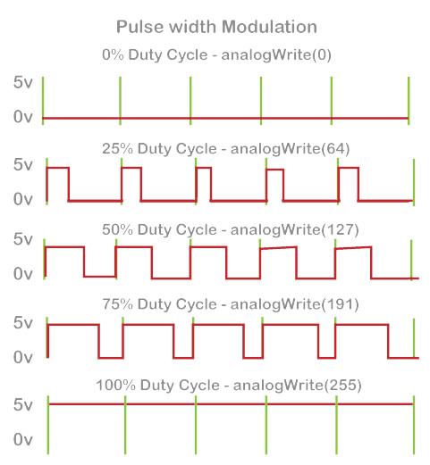
You can write an analog value (0 - 255) to a PWM pin by using the analogWrite() function.
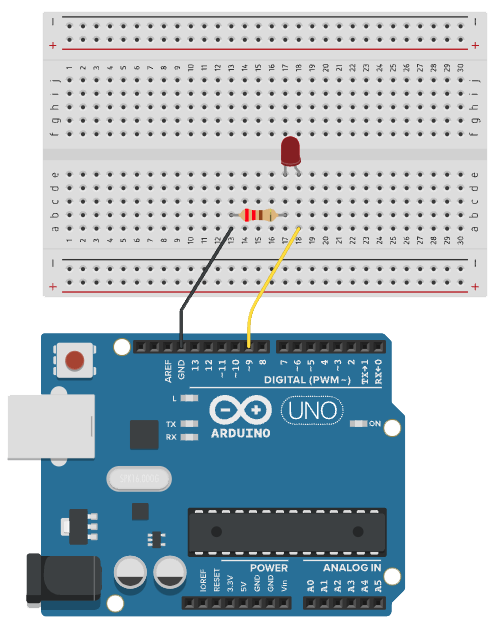
Example 2: Fading an LED with PWM
Objective: Learn how to control the intensity of an LED using digital pins by writing Pulse Width Modulation (PWM) signals.
Parts:
- LED
- 220 Ω resistor
- jumper wires
Code:
This is a variation of the Fading code that comes with the examples in the Arduino IDE (File > Examples > 03.Analog > Fading)
int ledPin = 9;  // LED connected to digital pin 9

void setup() {
  pinMode(ledPin, OUTPUT); // Set the pin as output
}

void loop() {
  // fade in from min to max in increments of 5 points:
  for (int fadeValue = 0; fadeValue <= 255; fadeValue += 5) {

    analogWrite(ledPin, fadeValue); // Set the duty cycle (0 to 255)
    delay(30); // delay to observe gradual change
  }

  // fade out from max to min in increments of 5 points:
  for (int fadeValue = 255; fadeValue >= 0; fadeValue -= 5) {
    analogWrite(ledPin, fadeValue); // Reduce brightness
    delay(30);
  }
}
Reading from Digital Pins
Similarly, one can read HIGH or LOW values from digital pins configured as INPUT.
This example reads the value (voltage) of a pushbutton and uses it to turn on an LED:
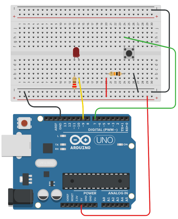
Example 3: LED with button
Objective: Learn how to detect a pushbutton (input) and have it control an LED (output).
Parts:
- LED
- Push button
- 220 Ω resistor (for LEDs, any from 220 to 1k Ω will work)
- 10k Ω resistor (for push button, acting as pullup resistor)
- male jumper wires
Code:
const int ledPin = 9;  // LED connected to digital pin 13
const int inPin = 7;    // pushbutton connected to digital pin 7
int val = 0;            // variable to store the read value

void setup() {
  pinMode(ledPin, OUTPUT);  // sets the digital pin 13 as output
  pinMode(inPin, INPUT);    // sets the digital pin 7 as input
}

void loop() {
  val = digitalRead(inPin);   // read the input pin
  digitalWrite(ledPin, val);  // sets the LED to the button's value
}
Pull-up resistors with pins configured as INPUT
Often it is useful to steer an input pin to a known state if no input is present. This can be done by adding a pull-up resistor (to +5V), or a pull-down resistor (resistor to ground) on the input. A 10K resistor is a good value for a pull-up or pulldown resistor.
There are 20K pull-up resistors built into the ATmega chip that can be accessed from software. These built-in pull-up resistors are accessed by setting the pinMode() as INPUT_PULLUP. This effectively inverts the behavior of the INPUT mode, where HIGH means the sensor is off, and LOW means the sensor is on. More about why using INPUT_PULLUP is helpful and examples.
Analog pins
The ATmega controllers used for the Arduino contain an onboard 6 channel analog-to-digital (A/D) converter (8 channels on the Mini and Nano, 16 on the Mega). The converter has 10 bit resolution, returning integers from 0 to 1023. While the main function of the analog pins for most Arduino users is to read analog sensors, the analog pins also have all the functionality of general purpose input/output (GPIO) pins (the same as digital pins 0 - 13).
Consequently, if a user needs more general purpose input output pins, and all the analog pins are not in use, the analog pins may be used for GPIO.
A code example of how analog voltage values are read:
void setup() {
	const int sensorPin = A0;
	int sensorValue = 0;
}

void loop() {
	sensorValue = analogRead(sensorPin);
}
Mapping analog INPUT values to PWM values
The analogRead() function reads 0-1023 and the analogWrite() function writes 0-255. So to make these values work together, use the map() function.
/* Map an analog value to 8 bits (0 to 255) */
void setup() {
	int analogPin = A0;
	int pwmPin = 9;
	int val = 0;
}
void loop() {
  val = analogRead(analogPin);
  val = map(val, 0, 1023, 0, 255);
  analogWrite(pwmPin, val);
}
LED controlled by photo-resistor
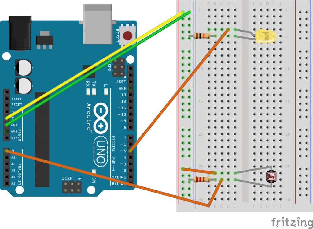
Code:
Found at: File > Examples > Analog > AnalogInput
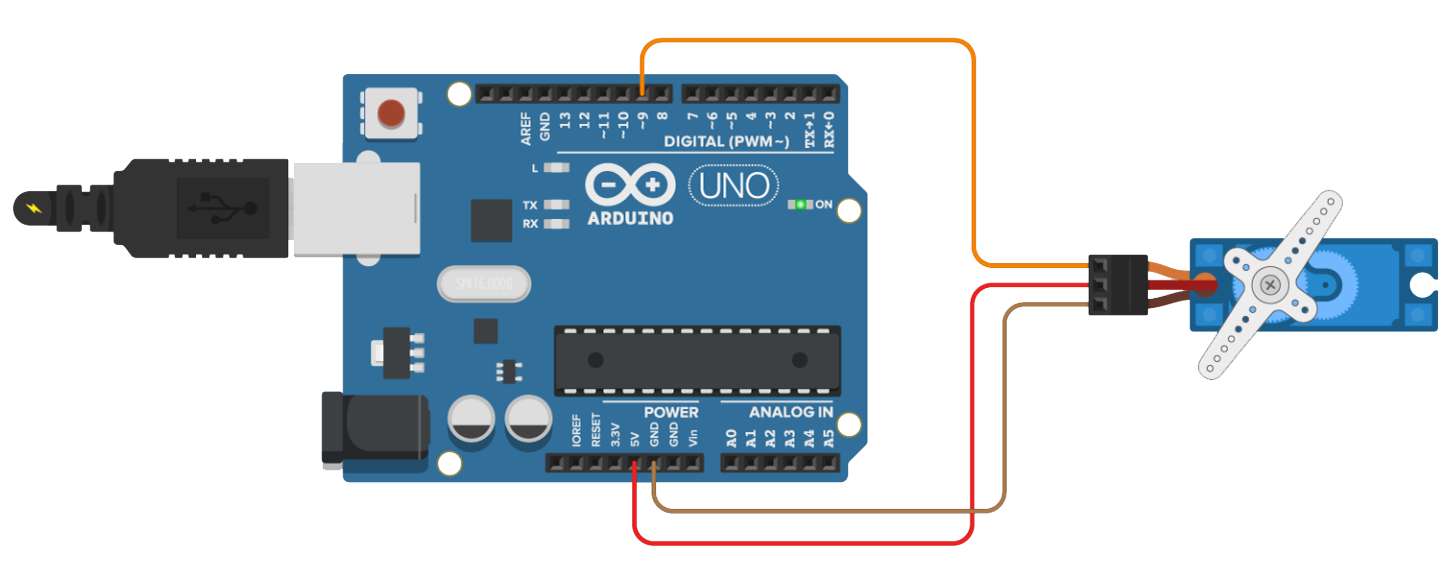
Postitional Servo
The servo represented in the circuit diagrams may not look exactly the same as the one in you are using, but you can assume that the black wire is GND, the red wire is 5V and the last one is the PWM signal.
Servo value range: 0 - 180
Requirements:
- Library: Servo
Parts:
- Positional servo
- jumper wires
Code:
File > Examples > Servo > Sweep
/* Sweep
 by BARRAGAN <http://barraganstudio.com>
 This example code is in the public domain.

 modified 8 Nov 2013
 by Scott Fitzgerald
 https://www.arduino.cc/en/Tutorial/LibraryExamples/Sweep
*/

#include <Servo.h>

Servo myservo;  // create servo object to control a servo
// twelve servo objects can be created on most boards

int pos = 0;    // variable to store the servo position

void setup() {
  myservo.attach(9);  // attaches the servo on pin 9 to the servo object
}

void loop() {
  for (pos = 0; pos <= 180; pos += 1) { // goes from 0 degrees to 180 degrees
    // in steps of 1 degree
    myservo.write(pos);              // tell servo to go to position in variable 'pos'
    delay(15);                       // waits 15 ms for the servo to reach the position
  }
  for (pos = 180; pos >= 0; pos -= 1) { // goes from 180 degrees to 0 degrees
    myservo.write(pos);              // tell servo to go to position in variable 'pos'
    delay(15);                       // waits 15 ms for the servo to reach the position
  }
}
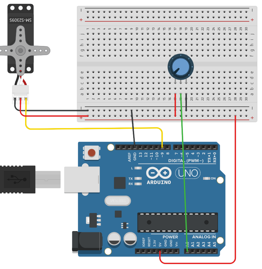
Positional Servo with Knob
Requirements:
- Library: Servo
Parts:
- Knob
- Positional Servo
- jumper wires
Code:
File > Examples > Servo > Knob
/*
 Controlling a servo position using a potentiometer (variable resistor)
 by Michal Rinott <http://people.interaction-ivrea.it/m.rinott>

 modified on 8 Nov 2013
 by Scott Fitzgerald
 http://www.arduino.cc/en/Tutorial/Knob
*/

#include <Servo.h>

Servo myservo;  // create servo object to control a servo

int potpin = A0;  // analog pin used to connect the potentiometer
int val;    // variable to read the value from the analog pin

void setup() {
  myservo.attach(9);  // attaches the servo on pin 9 to the servo object
}

void loop() {
  val = analogRead(potpin); // reads the value of the potentiometer (value between 0 and 1023)
  val = map(val, 0, 1023, 0, 180); // scale it for use with the servo (value between 0 and 180)
  myservo.write(val); // sets the servo position according to the scaled value
  delay(15);              // waits for the servo to get there
}
The analog input in this example, the knob, is interchangeable. In place of the knob, try:
- photodiode
- force sensitive resistor
- infrared sensor
- ultrasonic (ping) sensor
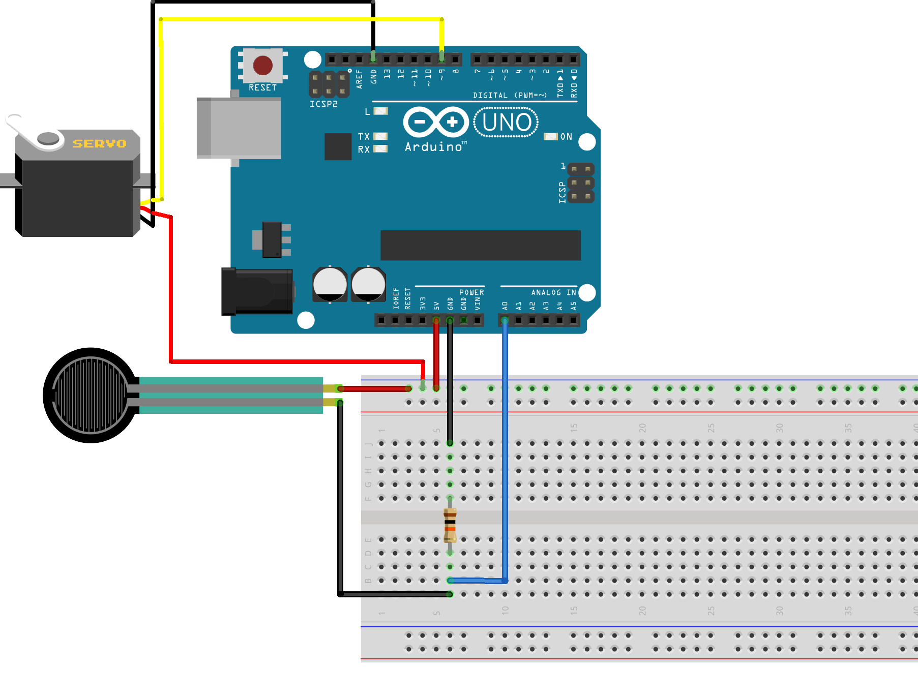
Servo and force sensitive resistor
Temperature/Humidity Sensor
The DHT11 sensor reads temperature and humidity. One can use the USB connection to communicate data back to the computer. This is called serial communication. You must initiate the connection at a specific baud rate (speed) and then data can be sent or received.
For communicating with Serial Monitor, make sure to use one of the baud rates listed in the menu at the bottom right corner of its screen.
// Establishing serial connection at 9600 bits per second
Serial.begin(9600);
Requirements:
- Library: DHT11
Parts:
- DHTxx Sensor
- jumper wires

Code:
#include <DHT11.h>

// Create an instance of the DHT11 class and set the digital I/O pin.
DHT11 dht11(4);

void setup()
{
    // Initialize serial communication at 115200 baud.
    Serial.begin(115200);
    Serial.println("TEMP AND HUMIDITY INITIALIZING...");
}

void loop()
{
    // Read the humidity from the sensor.
    float humidity = dht11.readHumidity();

    // Read the temperature from the sensor.
    float temperature = dht11.readTemperature();
    float ftemp = (temperature * 1.8) + 32;

    // If the temperature and humidity readings were successful, print them to the serial monitor.
    if (temperature != -1 && humidity != -1)
    {
        Serial.print("Temperature: ");
        Serial.print(temperature);
        Serial.print(" C ");
        Serial.print("(");
        Serial.print(ftemp);
        Serial.println(" F)");

        Serial.print("Humidity: ");
        Serial.print(humidity);
        Serial.println(" %");
    }
    else
    {
        // If the temperature or humidity reading failed, print an error message.
        Serial.println("Error reading data");
    }

    // Wait for 2 seconds before the next reading.
    delay(2000);
}
Controlling solenoids with and Arduino
You can use either a transistor or a relay as the switch to control a solenoid valve with an Arduino. Each option has its advantages and specific use cases. See Relays and Transistors as Switches
More permanent solutions
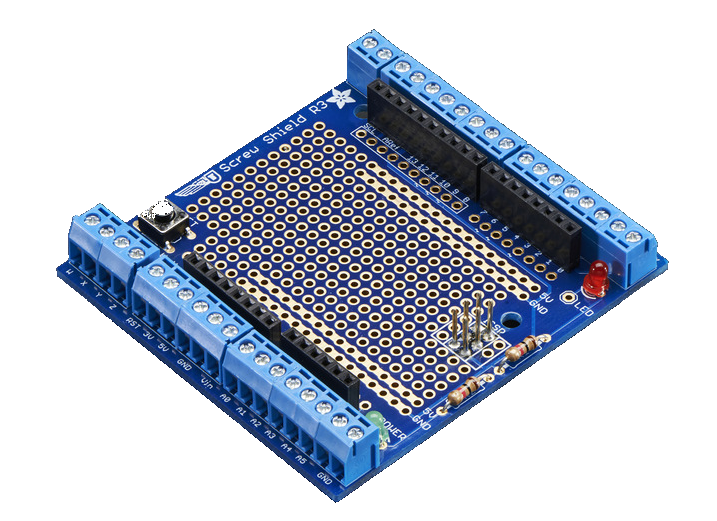
For securing wires more permanently consider using board with screw terminals.
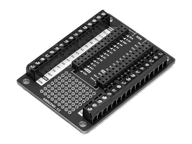
- Arduino Nano screw terminal adapter for longer term installations
- Custom PCB on the Othermill CNC
Project ideas
- ambient displays showing temperature, air quality, etc.
- switch relays
- self watering plant system
- sound reactive necklace
- RF projects:
- custom doorbell
- example of wireless communication between two Arduinos
- game controller
- active RFID
Conclusion
Congratulations on completing this tutorial! You've learned how to create circuits, upload code to an Arduino, and control components like LEDs and servos. Continue experimenting and exploring the resources listed to deepen your understanding of Arduino.
Don't try this at home
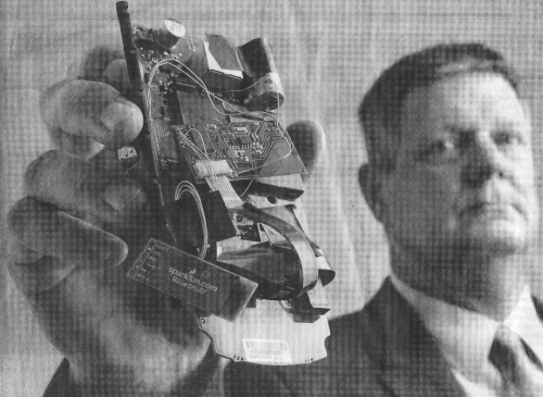
A SparkFun bluetooth transmitter found in a credit card skimmer in 2009.
More recently, at the request of a local government agency, SparkFun investigated how credit card skimmers work and what they are made of. Of course, I do not endorse creating anything like this but it is interesting to see how these work. They're not going away anytime soon.